Introduction
This article works as a guide for users developing Elipse applications based on Elipse E3, Elipse Power, and Elipse Water (whenever applicable) about the best practices for structuring, implementing, and managing these systems. We hope this document helps you better understand how to build an optimal-performance system that is easy to create and maintain. In addition, we strive for applications whose management has no issues exchanging data with other Elipse-based applications and other systems.
The structuring recommendations here follow the guide steps of ISA 95 standard. Its goal is to help define data interface templates and their functions. It’s structured after the Purdue model, which is based on the system’s hierarchy structuring.
In this document, we use examples from the buildings infrastructure area to illustrate various points. However, you can easily apply these same concepts to other segments in the industry.
Applications architecture
SCADA system applications built with Elipse platforms are developed for working in two types of scenarios: local applications, and distributed applications.
Local application
A local application has a single domain and is responsible for all monitoring in field devices (PLCs, IoTs, and others). In this structure, you will concentrate data locally, as seen in Figure 1.
Distributed application
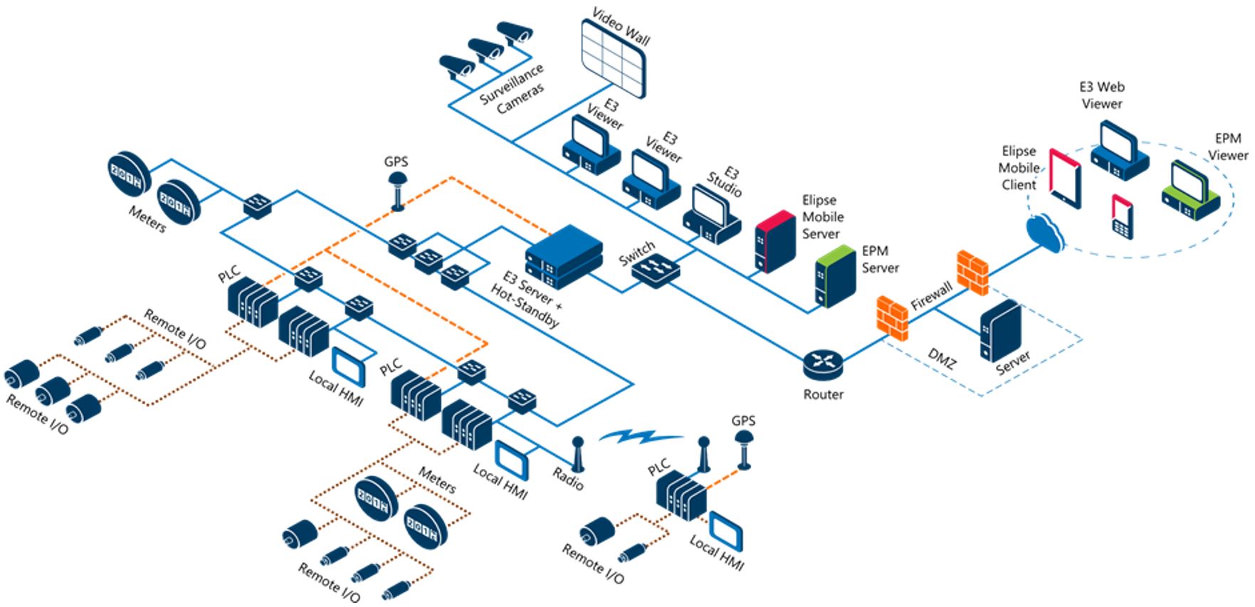
A distributed application features two or more domains exchanging data between each other. Usually, there is a core application for monitoring and/or controlling the whole plant. Thus, there can be local applications responsible for monitoring and/or controlling a certain process, as well as control centers that perform these same actions, even if geographically apart, as seem in Figure 2.
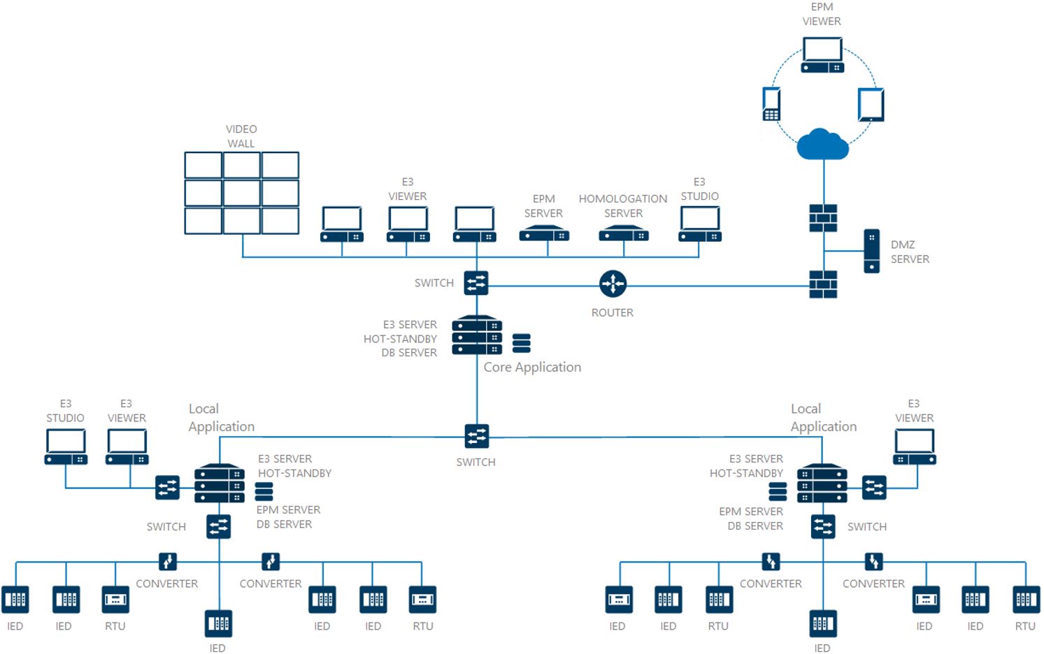
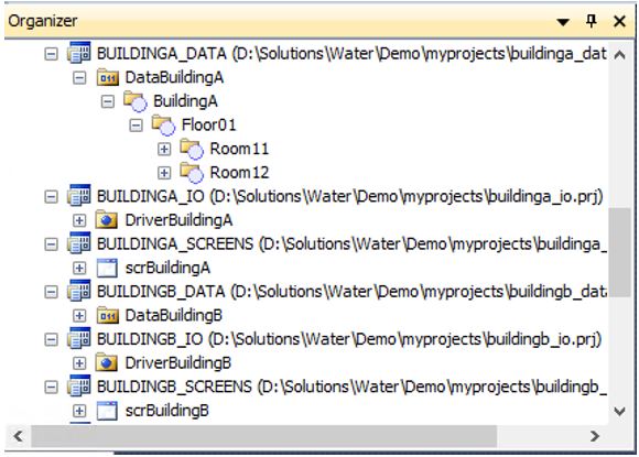
When using this type of application, you should pay extra attention to the names of root-objects added to the projects’s structures, including the name of files, as seen in Figure 2. You should mind these details in order to keep the system from malfunctioning. Throughout this article, we will bring to your attention other possible points of concern on this subject.
Managing library files
Managing Elipse E3 library files is a very important matter in distributed architectures. Most of the time, the same files are used both in core applications (control centers) and local applications (local operation). Therefore, is of the utmost importance for your system to implement a routine for controlling changes in files and keeping track of new versions. This will ensure your application runs smoothly in all areas of the solution. To do so, you can use tools such as Subversion, TFS, CSV, GIT, and Mercurial, among others. Thus, you can control new implementations, corrections, and improvements in order to avoid any conflict of versions. You can employ the same procedure for project files, ensuring better control and quality over system updates.
For further information on the subject, check out our article Version control for Elipse E3 project files.
Data exchange in distributed applications
When working with distributed applications, you will need to choose how the data exchange between applications will take place. Depending on that choice, you will have to take particular care during the development stage to ensure easy replication of files between systems (local and distributed).
Below, we describe the possible ways to exchange information in your application. Be sure to take extra care to maintain a good flow of updates, as well as to add new systems whenever necessary.
-
Direct communication with the controllers
From all data exchange models between Elipse applications, this is the simplest to use for managing the flow of updates in the system. In this format, the same driver configured in the local application is replied to the remote/core application. Therefore, you won’t have to perform any additional configuration while developing the application, because the local application can migrate almost intact to the core application. However, in order for this to happen, you will need a multi-master controller, that is, a controller that allows multiple connections directly to the device.
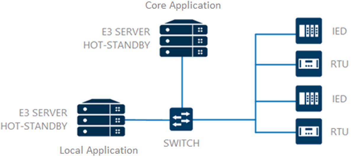
Figure 3 – Local and core applications communicating directly with controllers -
Direct communication with the local domain via driver
In this model, data exchange between core and local applications take place via communication driver. Therefore, the local application will first communicate with the controllers in the field. Then, the controllers will transfer these addresses to a second driver (slave or server), also configured in the local application, that will work as the connection point for the core application. The information exchange flow will look like the one in Figure 4.

Figure 4 – Controllers exchange data with the local application, which in turn replicates the information to the core application via communication driver There are two ways to achieve this:
a. The protocol (driver) collecting the information from the controllers is the same protocol of the slave driver, which will connect to the core application. When configuring this driver, you will only need to make sure the slave’s parameterizations are the same as the device’s. Thus, the driver’s connection project will remain the same for both local and core applications to facilitate the replication of projects.
b. The protocol (driver) of the local application connecting to the device is not the same protocol of the slave driver providing information to the core application. In this case, you will need to reconfigure the connection driver in the core application. To do so, it’s possible to read the controller’s data via its proprietary protocol, and then configure one of the two slave drivers in the local application. Therefore, the local application will have two drivers: one for configuring the data in the process and another one for connecting to the core application, as seen in Figure 5. This will ensure the transparency of the project’s communication, data, and interfaces structure, which in turn makes managing the updates easier.
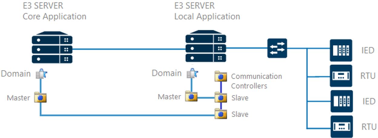
Figure 5 – Drivers gateway architecture For further information on this subject, we recommend checking out our article Elipse Gateway.
-
Communication between applications via OPC protocol
Another way to exchange data between applications and controllers is via OPC protocol. In this format, the local application connects to the controllers, and the core application connects to the local application via OPC protocol, as seen in Figure 6.

Figure 6 – Controllers exchange data with the local application, which replicates the information to the core application via OPC driver There are two ways to achieve this:
a. While the local application is built to connect to the controller directly, the core application needs to configure a new connection project for the OPC driver and the subsequent substitution of all connections to the OPC standard. To make migrating from local to core application easier, you can add a new, specific name to the data structure’s root folder (which mustn’t repeat on other levels/application points), and replace the addresses in the domain via Find/Replace tool. Anyway, when using this resource, you must make sure all the functions are working properly.
b. Another possibility, which is easier to manage, is to configure the local application to use an OPC “alias” to set up the application’s whole data. Therefore, you would only need to change the address of the OPC driver connection in the core application.
-
Communication between applications via Remote Domain protocol
Finally, the fourth and last model of data exchange between local and core applications is via remote domain protocol. This protocol is Elipse’s proprietary model; for further information, check out our article Remote Domains – Frequently Asked Questions (FAQ). This format works similarly to the one presented in the topic above (OPC Protocol), but it does not require creating a driver or tags to return the information from one application to another. This happens because, in this protocol, there is direct access to objects from the other application. That is: the local application connects to the controllers and the core application connects to the local applications.
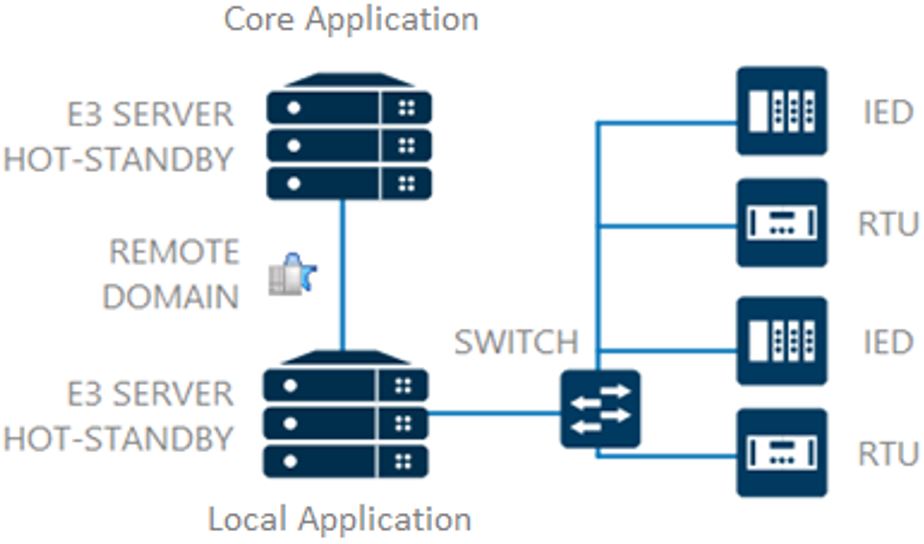
Figure 7 – Controllers exchange data with the local application, which replicates the information to the core application via Remote Domain To facilitate the management and development of applications, we recommend setting up the remote connection “alias” of the local application, that is, configuring the application via remote domain addresses. For further information, check out the article Using Local Alias to set up a Remote Domain server application.
Therefore, you can keep the transparency of configurations both locally and centrally. The only thing you will need is to reconfigure the destination of the remote domain connection when adding the local application to the core application.
Structure distribution of the core application
When the core application has a relevant amount of data to be processed by visual objects and/or server, we recommend the following in order to improve the application’s performance:
- Use a software platform with version x64 (this version allows using a larger amount of resources from the operating system).
- Split the processing of visual objects and E3 Server into different servers.
- Monitor how visual objects access the server objects, especially for low bandwidth networks.
For further information on this subject, check out our article Best practices for developing Elipse E3 applications.
Elipse Studio Tools
Verifying errors
To check for the existence of any issues in Elipse applications, there is a native tool from Elipse E3 called Verify. With it, you can check for configurations both in the application’s domain globally and in specific files (objects).
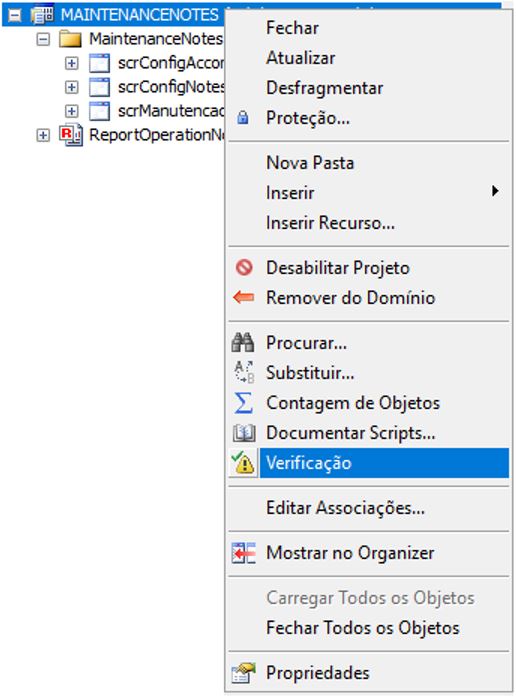
This tool retrieves all types of issues that were found in the configuration and also displays warnings pointing to possible future problems in the application. We use the word “possible” because there are configurations/logic programming which are based on the pre-existence of certain items. The application eventually solves them out dynamically, but the tool may point to them as errors. This type of notification usually takes place in libraries. Therefore, it is important to understand the application as whole so that you’re able to identify, from a list of errors, what to disregard and what to effectively act upon. In most cases, using this tool directly in project files will work as the best option for finding and fixing configuration errors.
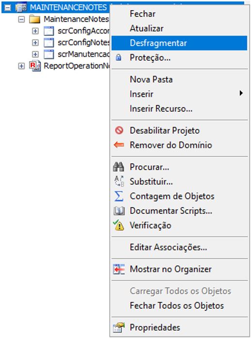
Defragmenting files
Application files (projects) are routinely edited and reconfigured. In these cases, similarly to what happens when storing files in disks in the operating system, new storage spaces are allocated in the application files. Therefore, merely removing them won’t automatically free up internal storage space. Thus, in this situation we recommend using the Defragment Files tool (Figure 9), because it will reconsolidate the items effectively used in the project while freeing up idle spaces.
Naming
The first step of building applications safely is to observe the names of all items in the structure, both project file names and the root items in them (folders, screens, etc.). Duplicated names entail usage errors, which will cause them to not execute. Therefore, choose compound names with underscores. For large compositions, use abbreviations, keeping in mind possible expansion scenarios for the system.
Organizing directories
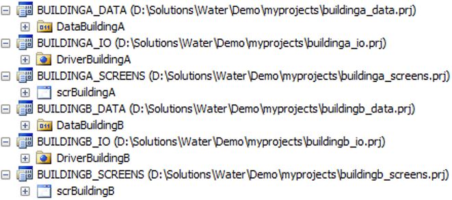
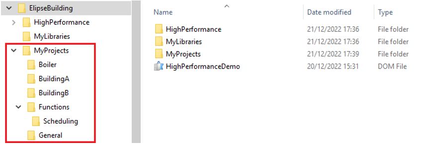
Another point to ponder while structuring a project is how to organize its directories. A tidy structure allows for very intuitive file replacement, especially in segmented or distributed systems. In Figure 11, you can see how to organize directories in an application for buildings. In the example, all buildings and their respective files are organized individually in folders with intuitive names related to the asset.
Organizing files
For higher efficiency incrementing and maintaining resources in Elipse E3 applications, we recommend segmenting the system into different project/library files, considering the supervised areas and their level of relevance to the system. So, the more you keep the items separated from each other, the faster you’ll succeed in initializing and updating items in the system. Also, you will have fewer unnecessary impacts at other points of the solution (Figure 12).
Understanding data objects
Before we approach the subject of modeling itself, it’s important to understand how each data object works in the context of an Elipse application. In this chapter, we’ll present a brief description of these objects and how to use them in applications.
Communication drivers
Communication drivers are objects that collect information from field devices (usually, each device requires its own communication driver) and map the address/information in tags or blocks that will interact with Elipse E3.
Via drivers, it’s possible to have direct access to information and, via tags, it’s possible to configure screens, alarms, recordings, etc. However, we don’t condone this practice, because in many scenarios, you will need to contextualize specific information from communication tags. For example, when reading digital signals grouped in word and/or dword, a context is required to understand what each signal means. Another common scenario is to have a controller that individually does not represent the whole system’s structure. Therefore, the user will need to alternate between several drivers in order to associate the tags to a process screen.
Thus, the communication driver is the return tool for process data, and the place where you must standardize the return of format for measurements/values. However, in order to to contextualize the process’s structure itself, the best scenario is to model it via Elipse E3’s data objects. Below, we will discuss the recommendations that provide context to the data structure.
Configuration for standardizing read value format
When standardizing the values to be read/written in the system, you may question how to adjust the values returned in the tags back into the default for the application (for example, how to adjust the values for flow reading to the l/s default). To use the default value configuration in the application, we recommend to adjust it directly in the communication tags, under Scale properties.
For further information, check out our article Working with scales in an I/O tag.
General Tags
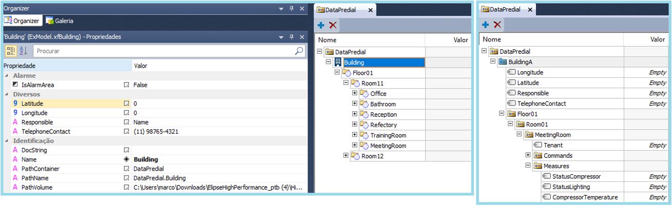
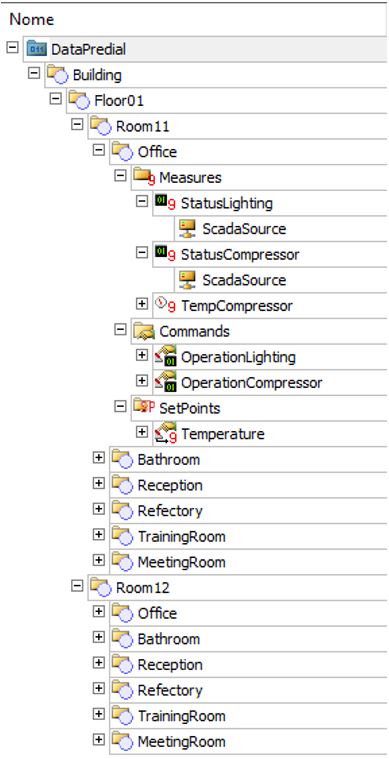
Elipse applications also provide tags for general usage: internal tags, demo tags, counter tags, and time tags, among others. These objects used to be employed to build hierarchy structures in previous versions of the software. But nowadays, using them causes the application to run too extensively. Many times, they make the system look “polluted”, as seen in Figure 13.
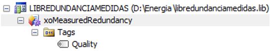
Ever since the creation of the object XFolder, in Elipse E3’s version 4.8, we have no longer recommended using general tags for modeling the system, only for specific cases according to each project’s own needs. In the example below (Figure 14), you can notice the measurement source has changed to reflect the quality configured.
Thus, we recommend using native objects when modeling Elipse Power or Elipse Water. As for Elipse E3, you should use XFolders and XObjects according to their specificities, as seen below.
XObjects
With an XObject, you can define a data structure and execute it in the server. This structure can perform calculations, associations, communications, alarm verifications, and historian records, among others. You should notice that they work essentially as end-use objects; for example, a control machine with all actions (commands, measurements, alarms, etc.) created inside this object. We don’t discourage its use; but currently, with the modernization of modeling objects, we recommend using it primarily for adding functions to end-use objects (Figure 14), in order to maintain hierarchy modeling and the general grasp of the application as much as possible.
XFolders
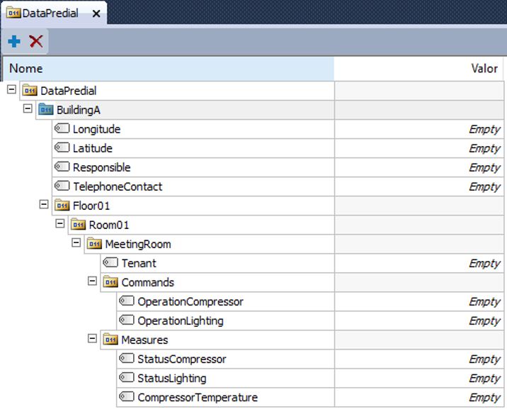
An XFolder is a server object that works as a “parent” to other external objects. From it, object’s hierarchy looks more organized and transparent. Therefore, you will avoid the need to create general tags (internal tags) for adding information, since you can add property to these data objects (Figure 15).
The advantages of working with hierarchy structure are:
- High flexibility for modeling items, because you can add specific information for each object/item in the application.
- Goes back and forward across its levels very easily and transparently, which allows quick access to all the needed information.
Modeling data objects in the server
Modeling for general applications
In order to model Elipse systems in platforms with specific tools for its segment (such as Elipse Power, developed for energy systems), we strongly recommend modeling the system(s) via the platform’s native objects.
For modeling applications in platforms with no native tools, we recommend using the objects of PlantModel library. This library will allow you to create countless general applications, in various different areas, due to its helpful resources, such as tracking command executions, configuring property history for EPM, and others. It’s also possible to create your own objects structure with XFolders, respecting the assets’s hierarchy, which is more flexible and adheres better to the concept of adding functionalities in the future, as seen in Figure 16.
For further details on PlantModel library, we recommend reading the document PlantModel Manual.
Inside the hierarchy structure, there are two possibilities for building the operation’s final object (machine, sensor, others):
- Following the hierarchy structure (XFolder), or
- Modeling/focusing the object’s functions (XObject).
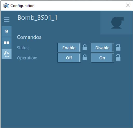
You must choose between these two options according to the application’s specific needs. However, take into consideration that in a hierarchy structure you can view the system as a whole and easily adjust its hierarchy. You can also count on native resources already available with Elipse libraries, such as Elipse HighPerformance. With this resource, you have access to a native screen, called Faceplate, used for operating assets (Figure 17).
Customized operation screens, or screens with objects not supported by Faceplate, must be developed by a programmer.
Adding data structure functionalities to the application
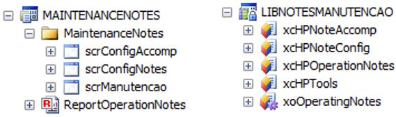
In order to add functionalities to the system, we must once again stress the recommendations from previous topics in this document: Whenever possible, functionalities must work independently. This means that for each new functionality added to the system, the projects/libraries file structure must be distinctive, so that their updates, corrections, and improvements don’t interfere with the functioning of other processes, or with the system as a whole (Figure 18).
Organizing the alarms in the application
There are two possible approaches for configuring alarms in the application: via hierarchy structure, or by adding alarms directly to the system’s alarms session. We’ll list below the pros and cons of each approach:
- Alarms in hierarchy structure:
Pros: alarm areas can be adjusted/configured more easily (for example, from context or from the hierarchy position held by each alarm).
Cons: alarms are not easily found in the edition area (E3 Studio); in some cases, support tools such as codes are required in E3 Studio or database. - Alarms in default structure:
Pros: the whole alarms structure can be easily located; items can be separated into different files.
Cons: most of the alarms will require longer configuration and update times.
Another possibility is to configure alarms inside the structures of XObjects. We’ll list below the pros and cons of this approach:
- Pros: objects modeled inside XObjects already come with alarms configuration: if any alteration is required, it can be done directly inside the class, thus all objects will be updated too.
- Cons: it can’t be customized or saved natively, only via the object’s support structure; it can be difficult to spot all the alarms in the system.
You can employ any of approaches above with no losses to the system. However, if you want a larger number of users, of all levels, to be able to understand and operate the system, we recommend using alarms in default structure.
Storing information
An increasingly essential functionality in automation centers is storing tags changes (historian). With it, it’s possible not only to understand the operation’s past and current behaviors, but also to project future actions that will allow improving it even more. In this scenario, using Elipse Plant Manager (EPM) is crucial. Our platform lets you aggregate several data management functionalities, perform enlightening analyses, and continuously improve the system, while bringing greater operational intelligence to the process.
The EPM platform also provides tools for recording application data automatically via PlantModel library. With it, you can select directly in the object’s/measurement’s definition which ones are recorded in EPM and which ones are not, via EnableHistorian property.
For further information about EPM, check out our articles about Elipse Plant Manager.
Creating screen interfaces
There are three different approaches to creating operational interfaces: by creating the visualization structure directly on screen, by using a library with XControls, or by working with layers or visibility. We don’t recommend any specific approach to building your interface, but keep in mind these recommendations:
- Avoid creating double visual interfaces via indexing the interface (for example, two equal interfaces to command the same engine).
- Use as few scripts as possible, and prioritize associations.
- Avoid constant accesses to the server, or accesses in larger scale. In this case, we recommend working with the server’s structure traffic via structured file.
Procedures for updates
Once the application is in run time, keep the domain from being interrupted at all costs, because all Elipse objects can update in run time, especially project files.
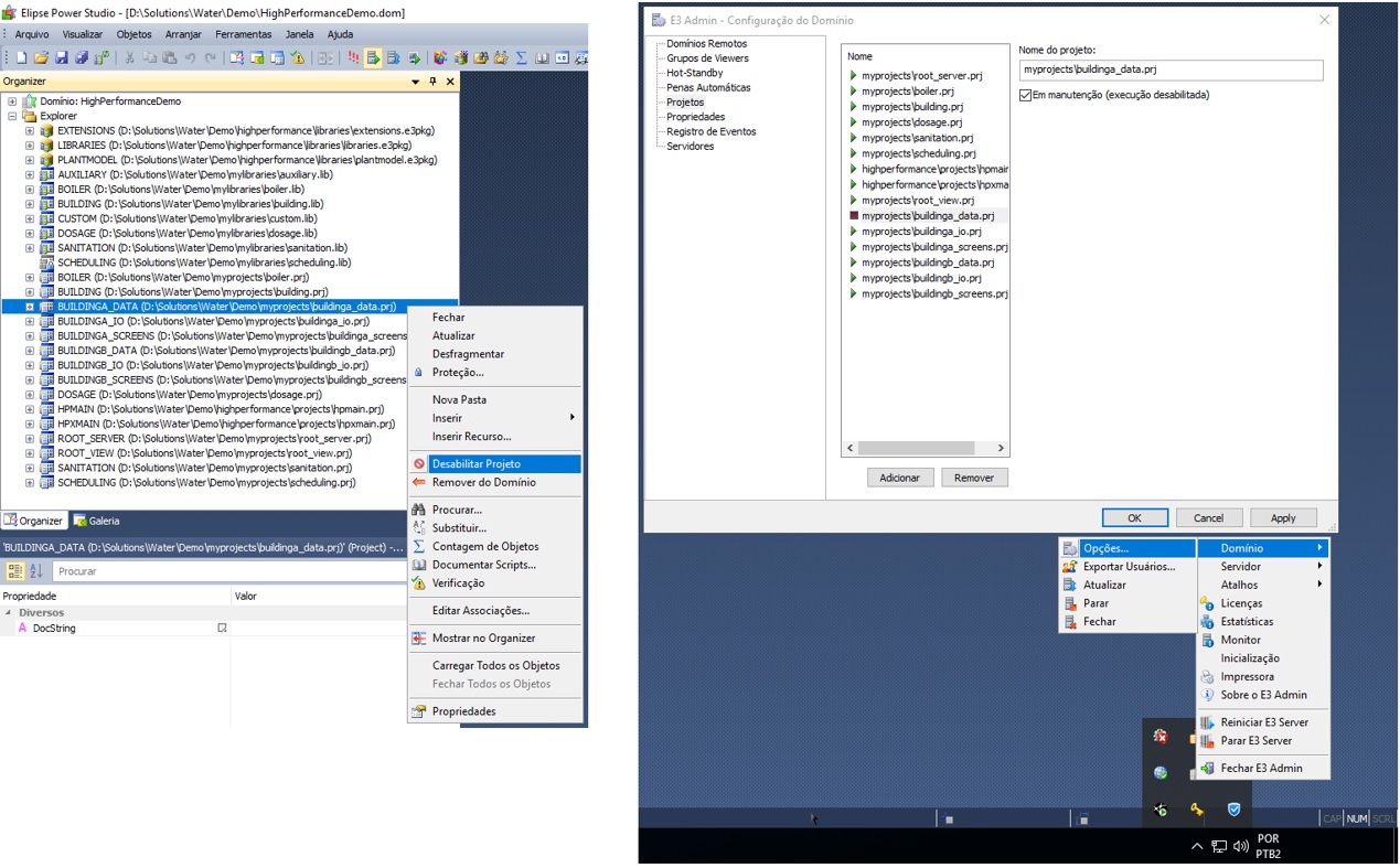
If necessary, you can stop a single file. In the example of Figure 19, you can stop a specific project in a specific area and not have it impact the others.
Libraries can also update in run time. However, if the object for update is shared by more than one project at the same time, all of them will restart. In this case, we recommend scheduling the updates.
For further information, check out the following articles:
- KB-32358: Refreshing the application without having to stop the domain.
- Remote applications maintenance in Elipse E3.
HotStandby
HotStandby implements a failover in the supervisory system. A failover implies the co-existence of two servers: a main server, and a backup server, both mutually contingent. That is: if the main server fails, the backup server will immediately be activated to replace it, with no loss for the process’s continuity.
For further information about this system, as well as a demonstration on how to update files in this structure, check out the following articles:
