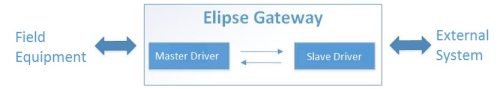
The Elipse Gateway feature provides a gateway via software which dismisses the need for any additional hardware and guarantees data transmission efficiency. This solution can be used by substations or generation units to report data to control centers and energy management agencies, or simply to exchange data between two systems.
This is Elipse Gateway’s structure:
To create a communication gateway between two drivers (master and slave) in the same application, follow the procedures seen in this article.
Basic Settings
To make sure all tags involved in this gateway are always communicating, you must set up AdviseType property as 0-AlwaysInAdvise in all variables used in the gateway, both in the master and in the slave drivers.
Elipse’s Slave Driver
Depending on the activation order of the objects instanced in the application, the slave driver may be activated before the master one, and this will cause the first value of each variable not to be received in the slave driver’s tags. Because of that, you will need to create a ‘re-initialization’ script for the slave driver’s tags.
To do so, access the slave driver, and create a script at AfterStart event to activate and deactivate all tags in the driver.
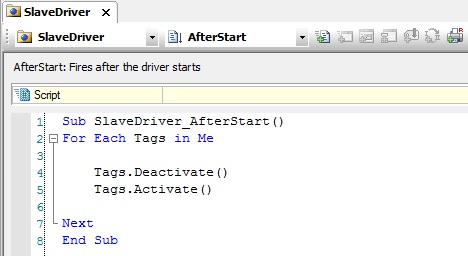
NOTE: Folders inside the driver will only need to be deactivated and then reactivated, and no internal scan is required for them.
I/O Tags
Read variables
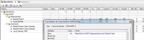
In situations when a value received by Elipse’s master driver needs to be made available for the external system, you will need to create a simple link in the slave driver’s tags to receive the value read by the master driver.
In addition, you will also need to set up the master driver’s variables to allow reading (AllowRead property), and the slave driver’s tags to allow only writing (AllowWrite property).
Write variables
1. Simple value write
Used when the external system requires a simple write or sending a device’s setpoint value, for example. Depending on the device, this must be written in the same status’s read variable, or then in a second variable created specifically for this purpose.
1.1. Same variable for both writing and reading
In this case, create a bidirectional link between the slave driver’s and master driver’s tags.
In addition, you must also set up the slave driver’s and master driver’s respective tags to allow writing and reading.
1.2. Variable for writing only
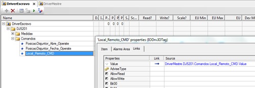
In this case, create a reverse link in the slave driver’s tags that send the value to the master driver.
2. Command sending write
Whenever you need to send commands to the device via external system, you will have to create scripts that interpret these commands and send them to the master driver.
For example: the external system has been set up to send value 65 (in a given variable) to indicate that a certain breaker must be closed; however, the device in the field is expecting value 1 to run Close command. Thus, the Elipse Gateway needs to convert this value before it is sent to the field device.
This script must be created according to the information in the slave driver’s manual. This can be done either on centralized or distributed mode, that is, the driver can be created either in a single place or directly in each driver. Additionally, you must also disable EnableDeadBand property in the tags that will receive the external commands so that all and any write commands received by the slave driver is handled by the driver.
2.1. Centralized script
In this scenario, you will create only one script to answer all commands sent. The driver has an event called OnTagRead that fires whenever a driver’s tag receives a new read (the option EnableDriverEvent must be on). This event receives as a parameter the tag receiving the read, which allows you to check which variable should continue receiving the commands. With this, the received commands can be all handled in a single place.
TIP: this script should be generated as generically as possible, and not have many If/End If or Select Case situations. You can set up a rule for the I/O tags names, and then create the script only to apply this rule to reach Elipse’s master driver’s tag.
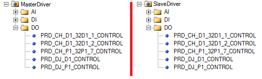
The example below illustrates how to create this script. Its goal is to repass to the master driver (whose tags are named the same as the slave driver’s ones) the same value received by the slave driver:
Sub DriverEscravo_OnTagRead(Tag)
TagMasterDriverName = Replace(Tag.PathName, “SlaveDriver”, “MasterDriver”)
set TagMasterDriver = Application.GetObject(TagMasterDriverName)
TagMasterDriver.WriteEx Tag.Value
End Sub
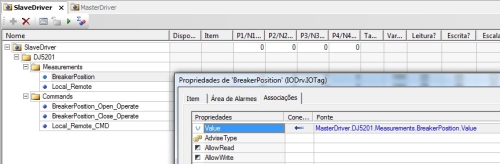
2.2. Distributed script
In this scenario, you will create one script in each tag receiving the external commands. At the tag’s OnRead event you will find the script responsible for interpreting the command’s request and send it to the tag in the desired Elipse’s master driver. In the example below, a write command is generated in the master driver at every new command received by the slave driver, both with the same value.
Sub PosicaoDisjuntor_Abre_Operate_OnRead
Application.GetObject(“MasterDriver.DJ5201.Commands.BreakerPosition_Open_Operate”).WriteEx Value
End Sub
Drivers’ Peculiarities
DNP 3.0 Slave
Receiving commands
The DNP slave driver can handle the commands received by the external command in three different ways (Command Response Profile option):
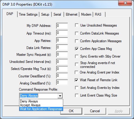
- Deny Always: all received commands will be denied. Basically, it forces the driver to not handle any external command.
- Accept Always: all received commands will be accepted and repassed to the I/O driver, and then the driver will let the external system know the command has been accepted. The application will only need to handle the value and decide what to do with the command.
- Wait for Application Response: all commands will be received manually. They are handled by the application, which is responsible for receiving, checking its acceptance, writing in other drivers (when necessary), and sending the return message to the external system.
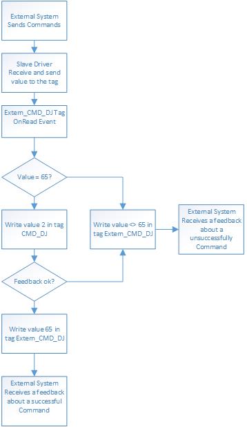
The example below illustrates how commands are handled when the application is the responsible for it. When the external system sends value 65 to Externo_CMD_DJ tag, the driver must write 2 at CMD_DJ tag.
For further information on procedures/scripts for receiving commands, please refer to the driver’s user manual.
IEC 870-5-101/104 Slave
Receiving commands
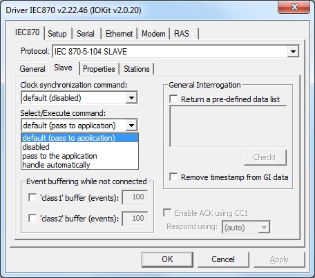
Similarly to the previous item, the IEC 101/104 driver also allows choosing how to handle the commands, with the same three options available. They can be set up on IEC 870 tab, Slave sub tab, Select/Execute command option:
- Disabled: all received commands will be denied. Basically, it forces the driver to not handle any external command.
- Handle automatically: all received commands will be accepted and repassed to the I/O driver, and then the driver will let the external system know the command has been accepted. The application will only need to handle the value and decide what to do with the command.
- Pass to the application: all commands will be received manually. They are handled by the application, which is responsible for receiving, checking its acceptance, writing in other drivers (when necessary), and sending the return message to the external system.
The example below illustrates how commands are handled when the application is the responsible for it. When the external system sends Execute to Externo_CMD_DJ tag, the driver must write 2 at CMD_DJ tag.
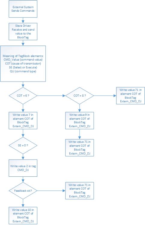
NOTE: COT = 71 means it wasn’t possible to proceed with the command’s activation/execution.
For further information on procedures/scripts for receiving commands, please refer to the driver’s user manual.
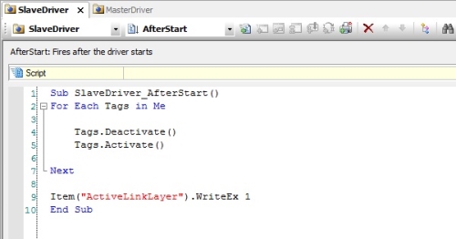
Slave mode initialization
In addition to what was discussed in the Slave Driver item, when working with IEC 101/104 protocols on slave mode, you can first set up the slave driver and only then initialize it. This ensures the driver will only be available to receive connections and exchange values when it’s already fully set up.
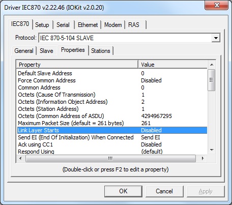
To do so, access IEC870 tab, Properties sub tab, and disable Link Layer Starts property:
Then, create a new tag in the application and set it up as: N1=0, N2=996, N3=0, N4=0, called ActiveLinkLayer (example).
At OnAfterStart event, after all tags have been deactivated and reactivated, write value 1 in the tag.