Introduction
Oftentimes, when developing applications with SCADA software, you will need to perform tests where I/O tags must be either forced or simulated. This article will show you how to develop an application with E3 that lets you simulate a PLC or any other device connecting to the supervisory software. To do so, we will use an OPC server running in a second computer, connected on a network to the main computer.
OPC client settings
There are two drivers in the main application. One of them is called Real Driver; this is the driver (Modbus, Profibus, etc., depending on the protocol adapted by the device) developed for communication with the field devices. The other driver is called Simulator Driver, and it is an OPC driver whose structure and names of elements are identical to Real Driver.
Note that these two drivers (Real and Simulator) cannot be used at the same time and in the same application, because their names and paths are the same. To keep them from being used at the same time, there are two possibilities. One of them is to add an extension to the name of one of the drivers, leaving the original name (the one linked in the application) just for the driver you want to use. Another one is to create a project containing only Real Driver, and a second project containing only Simulator Driver; to do so just remove the project that will not be used in the current domain. In this example, we will use the latter option, but in both cases you can exchange drivers without affecting the links to I/O tags created in the application.
When adding the OPC driver to the project, first make sure it is linked to the OPC server; this link must be activated automatically when running the domain of simCLP application, located in another computer in the network. To do so, just locate the OPC server (Elipse.OPCSvr.1) on the network, and then activate the communication.
Once it is done, click Import tags on the OPC driver’s folder. The tags created in the OPC Server can be dragged to the OPC Driver. Usually, you will only need to import the Value property of the server tags. After these tags have been imported, rename them and reconfigure them so that the OPC driver is identical to Real Driver. Thus, it will not be necessary to change the links that have already been created.
The link between OPC tags and the server can also be altered in the ItemID property of OPC tags.
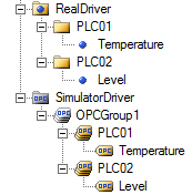
Figure 1 – Real Driver and Simulator Driver
OPC server (simCLP) settings
simCLP works as an OPC server that is activated automatically whenever the application runs, making all its tags available to an OPC client (main application). The application has four different I/O modules: Digital Input, Digital Output, Analog Input, and Analog Output. For each I/O point, there is tag identifying the input or output. The tags, as well as all settings, are saved whenever they are altered. So, when you open the application, it will load the last saved settings.
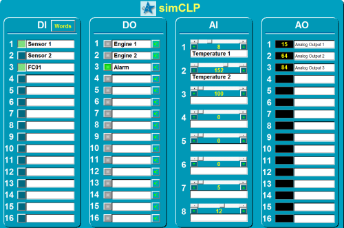
Figure 2 – simCLP’s main screen with its I/O points
Digital Inputs
Digital inputs can be used in two different ways. One of them is bit by bit, where each digital input corresponds to a communication tag. It is also possible to use them in word mode, where several digital inputs can be linked to make up a word representing, in decimal, the status of the digital inputs. In the latter case, you can transmit up to 16 digital input statuses with only one I/O tag. Both cases are illustrated below.

Figure 3 – Digital input
Bit by bit
No settings are required to use digital inputs in bit-by-bit mode. Just import Value property of tags DI1, DI2, …, DI16, located in DigitalInputs folder, to the main application.
Variable type: Boolean.
Word
Word mode can be set up via Words button, on the upper part of digital inputs module, on the main screen. There are five Words available for configuration. You must enable the word’s bits and link them to the digital inputs, and then import Value property of tags DI1, DI2, … , DI5, located in DigitalInputs_Word folder. In the main application, enable UseBitFields properties of the OPC tags linked to simCLP’s Word tags; this will cause the word to be broken into bits.
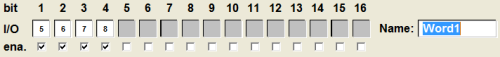
Figure 4 – Digital inputs settings on Word mode
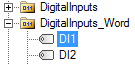
Figure 5 – Tag to be imported on Word mode for the settings seen previously
Digital Outputs
Similarly to what happens to digital inputs, digital outputs can also be used in two different ways: bit by bit or Word.
Figure 6 – Digital output
Bit by bit
No settings are required to use digital inputs in bit-by-bit mode. Just import Value property of tags DI1, DI2, …, DI16, located in DigitalInputs folder, to the main application.
Variable type: Boolean.
Word
In this mode, you can receive a word that stands for a set of bits in decimal format and then break it into bits. To do so, click ![]() . A window will be opened to configure this output. Enable its use in Word mode, choose the tag to be broken into bits, and select the bit to be linked to the current digital output.
. A window will be opened to configure this output. Enable its use in Word mode, choose the tag to be broken into bits, and select the bit to be linked to the current digital output.
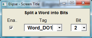
Figure 7 – Digital outputs settings on Word mode
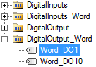
Figure 8 – Tag to be imported on Word mode for the settings seen previously
Analog Inputs
Analog inputs’s variables are accessed by importing variables AI1, AI2, …, AI8, from AnalogInputs folder. The only required settings are higher and lower limits, which define the analog variable’s range. They can be set via ![]() and
and ![]() buttons. The analog value can only be changed in the scrollbar corresponding to each AI (Analog Input).
buttons. The analog value can only be changed in the scrollbar corresponding to each AI (Analog Input).
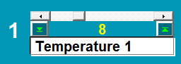
Figure 9 – Analog input
Analog Outputs
Analog outputs’s variables are accessed by importing variables AO1, AO2, … , AO16, from AnalogOutputs folder. No settings are required for analog outputs.
Figure 10 – Analog output
Final Remarks
This sample application shows an easier way of simulating a device communicating with E3. However, the application can be customized to suit each user’s needs. With simCLP, we have opted to use an OPC driver because OPC communication between two applications is very simple, but other drivers could be chosen in this case, such as Modbus Master/Slave, for example.
Attachments:
