1) Introduction
In part I of this article we saw the correct way to create links for animation of the screen controls. In part II, we discuss the best strategy for developing an application for an imaginary industrial plant.
2) Description of the plant
The plant of this example has two tanks (each with a valve that allows the liquid to enter) and a pump in the exit. By clicking the valve, the tank starts to be filled; by clicking the pump, the tank is emptied.
When opened, each valve becomes green and their legend displays the word “Opened”; when closed, they become red and their legend displays “Closed”. The pump, on its turn, becomes green displays a legend with the word “On” when it is on, and becomes red and displays “Off” when it is off.
Next, there is a layout of the plant.
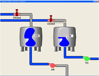
Picture 1 – Industrial plant with two tanks
3) Developing the object library
The first step for developing an E3 application is to determine which functionalities of the process will be repeated and can be transformed into E3 objects.
In this application you can easily see which screen objects are repeated: tanks, pumps, valves, and pipes. After the objects have been identified, it is necessary to define each of their functionalities and properties, as well as their design.
It is also necessary to execute tank working logic in the server. This logic is defined in a XObject, called “TankLogic”.
Next, you will see how to create each of these objects.
Creating the TankLogic XObject
Initially, you will create a project called Plant, with a library called PlantLib. The definitions of the XObjects and XControls will be in PlantLib library. The objects executed in the server and the Viewer screens will be in Plant project.
The TankLogic object (Figure 2) will have three properties to control tank process: ValveOpened informs whether the valve in the entrance of the tank is opened; Meter informs tank’s liquid level; and PumpActivated reports whether the pump in the exit of the tank is on.
An important tip for this step of the process is to fill the “Help text” column of each property added to an ElipseX (Figure 2). Each property’s text will then be shown in the AppBrowser, helping you maintain the application in the future.
For the purposes of this article, we will not go into many details on this object’s implementation; you should only know that when ValveOpened property is True, the tank starts to be filled up until Meter property reaches the limit of 100 units. When the PumpActivated property is on, the pump in the exit is on and the tank is emptied. When the pump is on and the valve is open, Meter property’s value remains the same.
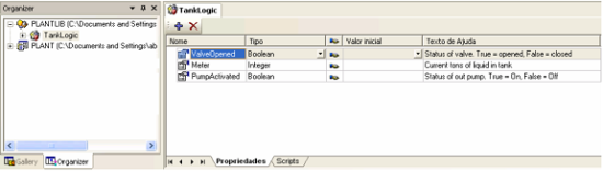
Picture 2 – TankLogic object’s definition
Creating the XControl Tank
The Tank object is made of the drawing of a reservoir and of two counters displaying liquid amount, one with an analog vertical bar and the other with the value in tons in the tank (Figure 3).
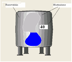
Picture 3 – Tank object
To show you how flexible ElipseX libraries are, the Tank object will be divided in two parts: one with the drawing of the reservoir, and the other with the drawing of the counters. Thus, you will be able to see that an ElipseX object can be made of other pre-existing objects.
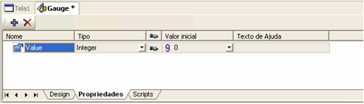
Picture 4 – Definition of the Value property of the Gauge object
The Gauge object contains the counters, and has a property called Value (see Figure 4), that will be used to animate the object’s internal controls. The drawing of Gauge object is in Figure 5.
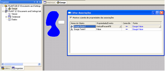
Picture 5 –Gauge object’s links
Notice that the two objects forming the Gauge are linked to Gauge’s Value property. This means that whenever Gauge’s Value property changes, this value will be sent automatically to the two objects linked to this property.
Now, we will see Tank object itself. The object is made of the drawing of reservoir and Gauge object (Figure 6).
Picture 6 – XControl Tank’s definitions
Next, we will handle the properties of this object. There are two different approaches for this: you can either add an Integer type property and link it to Gauge1’s Value property, or create a TankLogic type property and link Gauge1’s Value property to TankLogic’s Meter property.
For this example, we will choose the second option (Figure 7).
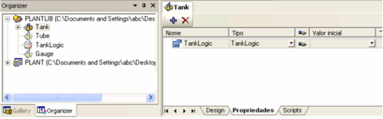
Picture 7 – Tank object’s TankLogic property
Now, all you have to do is link Gauge1 object’s Value property to TankLogic’s Meter property (Figure 8). This is how Gauge1 object will access the properties of the external object linked to TankLogic property.
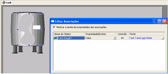
Picture 8 – Tank object’s link
Creating the XControl Valve
The Valve object is made of the drawing of a valve that is red when the valve is closed and green when it is opened. By clicking on the object, it switches the current state of the ValveOpened property linked to the TankLogic object, either opening or closing the valve.
The first step to build this object is to create a TankLogic type property called TankLogic, and then linking this object to a TankLogic object in the server.
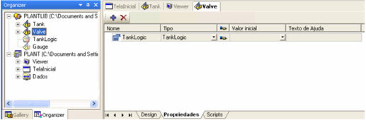
Picture 9 – Valve object’s TankLogic property
Next, there is the drawing of the Valve object and its links (Figure 10). You can observe that both and Figure1 were linked to Valve’s TankLogic ValveOpened property.
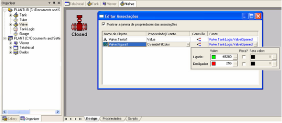
Picture 10 – Valve object links
Now you need a script that switches TankLogic’s ValveOpened property by clicking on the valve. This is done via a Click () script in Figura1 object (Figure 11).
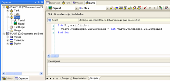
Picture 11 – Click script
Creating the XControl Pump
The Pump object is nearly the same as the Valve object, but two things are different: its drawing is a pump, and it switches TankLogic’s PumpActivated property (Figure 12).
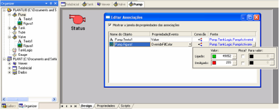
Picture 12 – Pump object’s links
4) Building the application
Once the library is ready, you need to add the objects to a project. To do so, you will have to create them in the Plant project. Since the application has two tanks, you will need two tank process simulators; therefore, it is necessary to create two TankLogic objects in the folder Data Server (Figure 13).
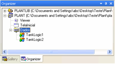
Picture 13 – TankLogic objects instanced in the server
Both objects, TankLogic1 and TankLogic2, will be later linked to the screen objects working as interface with the user for the opening/closing of the valve and connection/disconnection of the pump.
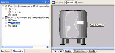
The objects created in the library, such as tanks, pumps, valves, and pipes, will be inserted onto the InitialScreen (see Figure 14). Each object will be linked to its respective TankLogic.
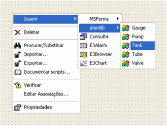
Picture 14 – Inserting the Tank object onto screen
The last step developing this application is linking the screen objects to their respective TankLogic objects (Figure 15).
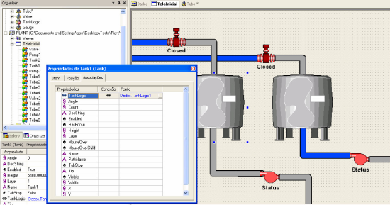
Picture 15 – Linking Tank1 object to Dados.TankLogic1
You can see how easy it is to create and maintain applications using the library resources in E3. After the library has been created, you can just create objects and their links, which facilitates your work enormously.
Notice that the library only keeps objects’ definitions; you should insert them in the project and configure their properties to have them working properly.
5) Conclusion
We saw in this application how simple and fast it is to create functional objects with the use of E3 libraries. With them, the paradigm of having to create the whole application from scratch is broken, because you can re-use objects previously used in other applications.
