1) Defining project’s architecture
First, the programmer must ask these questions: “Which parts of the application will be repeated?”, “How could I return values in parameterized objects?”
The most common answers to these questions are:
- Screen objects, such as pumps, valves, elevators, silos, etc.
- Screens, with different parameters (tags linked to objects).
- Data objects, such as alarms, tags, historic, etc.
But even by creating these exact objects, you may wonder: “Which are the advantages of this work?”. Let’s see:
- Everything is in one source (the definition can change and the place where it is used is automatically modified).
- Objects are made from other objects.
- Creation of properties.
- Reusing objects in other projects.
You will notice that as you get used to using E3 libraries, you will gain more engineering time through the improvements of objects; therefore, by modifying the library, the application is also automatically updated.
However, before emphasizing object creation, we have to review how links are used in properties.
2) Basic concepts for developing objects
For objects development, you will first have to understand basic concepts on links, animation resources, and how they are used inside E3. To do so, some problems will be presented as examples of what you should and should not do.
Problem 1: I want to have a text displaying the word “On” when the linked tag is 1, and “Off” when the linked tag is 0. Also, these words must respectively be green and red.
You should NOT DO this: create two Text objects: one in green and one in red; one in top of the other; and linked to the same tag’s Visible property, but in reverse:
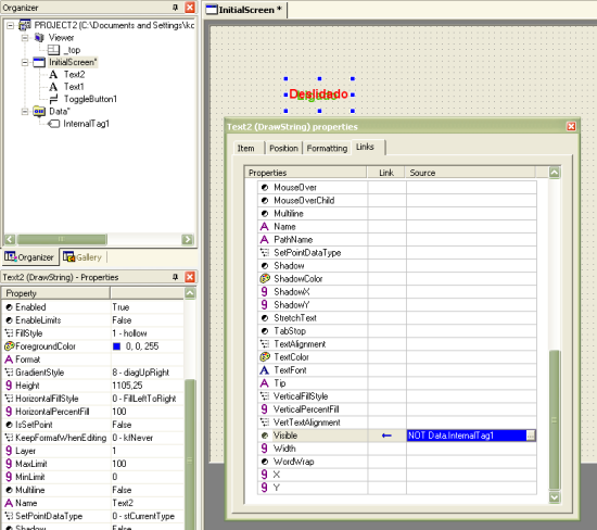
Picture 1 – Incorrect configuration of an on/off set
For only one on/off setting text this may seem simple, but imagine having something like this:
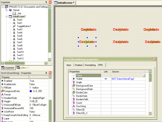
Picture 2 – Incorrect configuration of several on/off sets
With only 6 sets we have no less than 12 objects and 12 associations. It seems that editing the application gets complicated, because there are overlapping objects. For example, if the name of the tag linked to set changes, we will have to update it both links.
You should DO this: create only one Text object, with two links:
- Digital link between Value property and tag. This will set the value “On” when tag is 1, and “Off” when it is 0.
- Digital link between TextColor property and tag. This will set the value green when the tag is 1, and red when it is with 0.
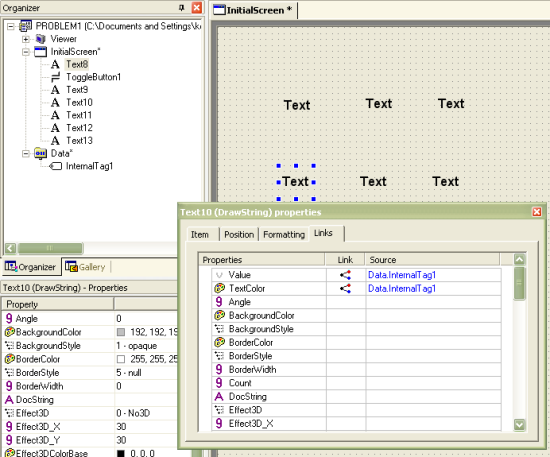
Below, there is the configuration of Value’s property digital link:
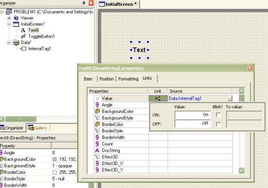
Picture 3 – Proper configuration of the link Value for the on/off object
And here is the digital link for TextColor property:
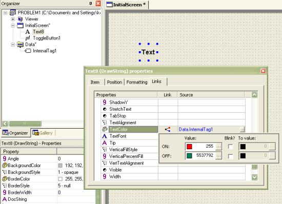
Picture 4 – Correct configuration of the association TextColor for the object on/off
Just like in the previous example, we will create five more copies to visualize them:
Picture 5 – Correct configuration of some sets on/off
Thus, it is possible to see the benefits of linking properties to only one object, instead of two:
- Now there are only six objects on the screen.
- Its edition became easier, because there are no overlapping objects, and color configuration is only in one place.
- In case tag name changes, you will only need to change the two links in only one object.
However, wouldn’t it be better if you could make these modifications all in only one place? This question will be answered later with the use of libraries.
Problem 2: How can I make the drawing of a truck run along a pre-established path according to tag value variation? Tag value goes from 0 to 3.
You should NOT DO this: create four trucks (DrawPicture objects) and configure a simple link between the tag and its Visible property in each one of them. Make sure tag’s True condition varies a little.
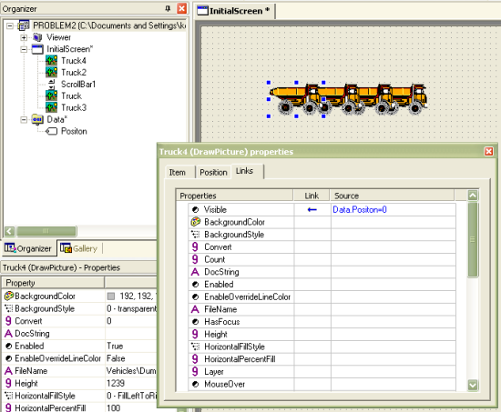
Picture 6 –Incorrect configuration of the first truck in the animation
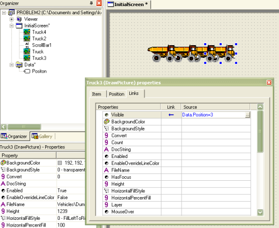
Picture 7 – Incorrect configuration of the last truck in the animation
This way to deal with the problem works perfectly, but it is not optimized, because:
- It creates four different links to the source (and if the source moves, you will have to change the four links).
- If tag value’s precision is increased in the future (with a bigger number of combinations), you will have to place more trucks;
- If the object’s initial position has to be altered, other objects will have to be moved as well.
Another possibility, a little more optimized than this, is to have just on object, and create an analog link between the truck’s X property and the tag, as follows:
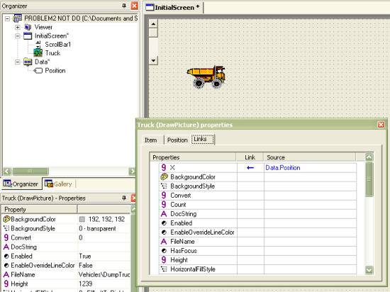
Picture 8 – Slightly improved, incorrect configuration of the truck’s animation
As configured above, E3 will convert tag value into property value; so, when tag varies from 0 to 3, the values between 500 and 5000 will be attributed to the truck’s X property, which will start the movement.
However, this solution still poses a problem: how do you know for sure where the animation ends? Here is the answer:
You should DO this: select the image and click on button “Animate with Translation” button. E3Studio will create a “ghost” image of the drawing indicating its final position. You should notice that “truck” object is placed inside a new object, called DynamicMove in the Organizer. The green square in the center of object will place it where intended.
Configure DynamicMove’s RangeMax and RangeMin properties to “3” and “0”, respectively. Create a simple link between tag and Value property, as seen below:
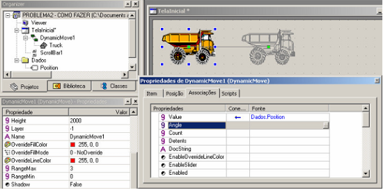
Picture 9 – Correct configuration of the truck animation
This will make the object automatically move from a place to another. This brings the following advantages:
- The “ghost” image indicates the final position of the truck in a clear, intuitive way.
- If you need to move the object’s initial position, its final position will also automatically be moved.
- It is possible to test the movement by changing the value of DynamicMove’s Value property during E3Studio edition.
Problem 3: How can I animate a pump’s status by changing its color? For example, let’s say I have three different states: “on”, “off” and “in maintenance”, represented by the colors green, red, and gray respectively.
You should NOT DO this: create three bitmaps with the three colors and make a simple link between tag and Visible property (similar to problem 1). Each bitmap’s color is configured as transparent color:
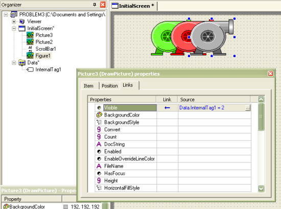
Picture 10 – Incorrect configuration to change the color of a pump
In this example, the pumps were placed side by side place for clarification purposes, because they would actually have to be overlapping. This way to deal with the problem contains the following problems:
- There are three different bitmaps; if you want to change on of the drawings in the future, you will have to change all three. For example, if you want to change its color from green to blue when the pump is on, you will have to modify the source bitmap.
- There are three links for the same tag; if tag name changes, you will have to modify it in all three links.
- Object edition also gets complicated, because there are three overlapping objects.
You should DO this: in E3, you must always give the priority to .WMF (Windows MetaFile) format, because you can modify some of its features such as color and fill type without having to change the source file. To solve this problem, place the WMF on the screen and make a table link between OverrideFillColor property and the tag:
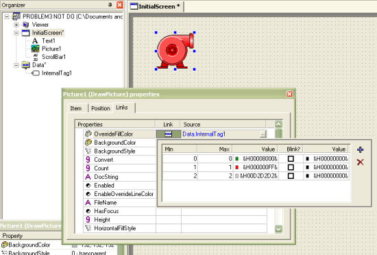
Picture 11 – Correct configuration to change pump color
In addition to the benefits that have already been explained in Problem 1, using .WMF files instead of bitmaps have the following advantages:
- You can redefine the .WMF’s fill type via OverrrideFillMode property to “Wireframe”, “SolidFill” or “ByBrightness”.
- You can redefine the .WMF’s fill color.
- You can redefine the .WMF’s border color.
- The picture is vectorial, therefore it will not lose resolution when zoomed.
As we have said before, all these modifications in the drawing do not modify the original file, only the way the drawing is visualized.
You may ask yourself: but what will happen if I need to have several of these objects configured in my application and need to modify their definitions after some time? Do I have to change them one by one? All these doubts will be clarified in Part II of this document.
