1) Introduction
Part I of this article introduced the proper way of creating links for animating screen controls. Part II will discuss the best strategy for developing an application for an imaginary industrial plant.
2) Plant description
The plant in this example comprises two tanks, each featuring a valve for liquid input and a pump for output. To fill the tank, click the valve, and to empty it, click the pump. When opened, each valve turns green and displays the legend “Open”. Otherwise, it turns red and displays “Closed”. Pumps, on the other hand, turn green and display the legend “On” when opened, or turn red and display “Off” otherwise. The figure below summarizes the plant.

Figure 1: Industrial plant with two tanks
3) Developing the objects library
When developing an application in Elipse E3, the first step is to establish which functionalities in the process will be repeated and also which can be designed as E3 objects.
In this application, it is clear which screen objects will be repeated: tanks, pumps, valves, and tubes. After spotting these objects, you will need to set up their functionalities, properties, and design.
The logic for tank operation must also be executed in the server. This logic is set up at an XObject called TankLogic.
Let’s see how each object is developed individually.
Creating TankLogic XObject
Initially, we will create a project named Plant with a library called PlantLib. This library contains the XObjects’ and XControls’ settings. The Plant project contains the objects executed in the server and the Viewer screens.
The TankLogic object (Figure 2) displays three properties for controlling a tank’s process: ValveOpened, which informs whether the tank’s input vale is open or closed; Meter, which informs the tank’s liquid level; and PumpActivated, which reports whether the tank’s output pump is on or off.
TIP: fill out the Help Text column for each property added to an ElipseX (Figure 2); this text will be displayed in the AppBrowser, and will further help with the application’s maintenance.
For this article’s purposes, we will not discuss the details of implementing this object; all you need to know is that when ValveOpened property is True, the tank will start filling up until Meter property reaches a 100-unit limit. When the output pump is turned on via PumpActivated property, the tank is emptied. When the pump is on and the valve is open, Meter property’s value remains constant.
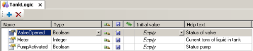
Figure 2: Setting up TankLogic object
Creating Tank XControl
Tank object comprises a drawing of the reservoir and two more displays for the amount of liquid, one with an analog vertical bar and the other with the value in the tank in tons (Figure 3).
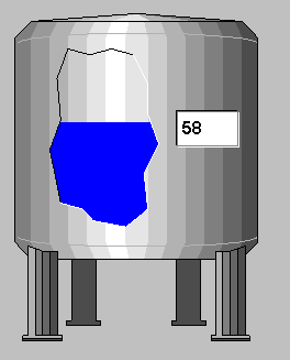
Figure 3: Tank object
To demonstrate the flexibility of ElipseX libraries, we will split Tank object in two parts: one containing the reservoir, and the other containing the displays. With this, you will be able to see how an ElipseX object can be built from other objects previously created.
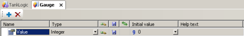
Figure 4: Setting up Gauge object’s Value property
Gauge object contains the displays and has a property called Value (see Figure 4), which will be used to animate the object’s internal controls.
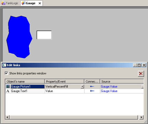
Figure 5: Gauge object’s links
Notice that both objects that make up Gauge are linked to its Value property. Therefore, whenever Gauge‘s Value property is edited, this value will automatically be sent to both objects linked to this property. Next, you can see Tank object, which comprises the drawing of the reservoir and the Gauge object (Figure 6).
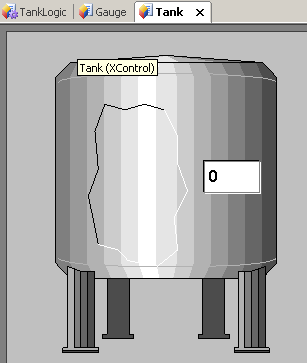
Figure 6: Tank XControl’s settings
Then, you will need to think of this object’s properties. There are two possibilities: in the first one, you can add an Integer property and link it to Gauge1‘s Value property. In the second one, you will create a TankLogic property and link Gauge1‘s Value property to TankLogic‘s Meter property. This example shows you how to perform the second option (Figure 7).
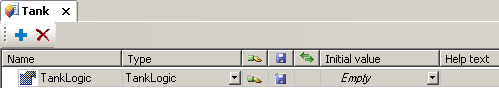
Figure 7: Tank object’s TankLogic property
Now, all you have to do is link Gauge1‘s Value property to TankLogic‘s Meter property of Tank object (Figure 8). This is how Gauge1 object will access the properties of the external object linked to TankLogic property, which is a TankLogic-type object.
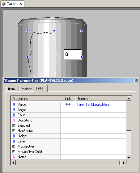
Figure 8: Tank object’s links
Creating Valve XControl
Valve object presents the drawing of a valve that turns red when closed and green when open. By clicking the object, it inverts the current status of the associated TankLogic object’s ValveOpened property, thus causing the valve to close or open.
The first step for building this object is creating a TankLogic-type property called TankLogic, thus allowing this object to be linked to a server’s TankLogic object.
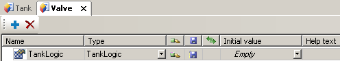
Figure 9: Valve objects TankLogic property
Next, we see Valve object and its links (Figure 10), where you will be able to see that both Text1 and Figure1 objects are linked to Valve‘s ValveOpened property.
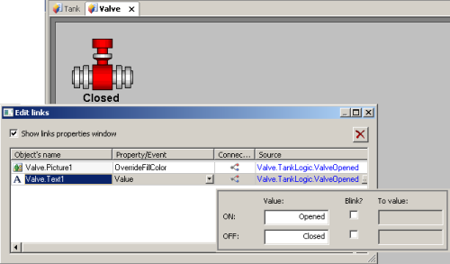
Figure 10: Valve object’s links
Now you will need a script that inverts TankLogic‘s ValveOpened property when clicking the valve. This can be achieved with a script at Figure1‘s Click() event (as seen below).
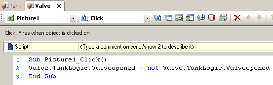
Figure 11: Script at Figure1‘s Click() event
Creating Pump XControl
Pump object is very similar to Valve object, but there are two main differences: its drawing is a pump, and it inverts TankLogic‘s PumpActivated property (Figure 12).
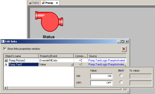
Figure 12: Pump object’s links
4) Building the application
Once your library is ready, you will need to insert the objects created in a project. To do so, just create the objects at Plant project as needed. Since there are two tanks in the application, you will need two tank process simulators, therefore you will need to create two TankLogic objects in the server’s Data folder (Figure 13).
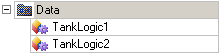
Figure 13: TankLogic objects instanced in the server
Both objects, TankLogic1 and TankLogic2, are then linked to the screen objects, which are the user’s interface for opening/closing the valve and turning on/off the pump.
You will add the screen objects created in the library (such as tanks, pumps, valves, and tubes) to the InitialScreen (Figure 14). Each object will be linked to its respective TankLogic.
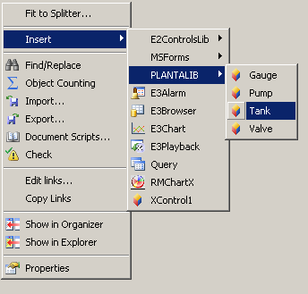
Figure 14: Inserting Tank object to the screen
At the last stage of developing this application, you will link the screen objects to its respective TankLogic objects (Figure 15).
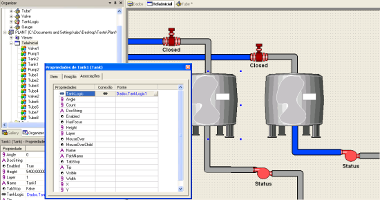
Figure 15: Linking Tank1 object to Data.TankLogic1
As you can see, it is easy to create and maintain applications using library resources in E3. Once the library is created, all you need is to create and link the objects, which greatly facilitates the work.
Notice that the library contains only definitions and not the objects per se, so you will need to insert them in the project and set up their properties so that they will work properly.
5) Final Remarks
With this application, you can see how easy and quick it is to create functional objects when using E3 libraries. With them, you don’t have to create a whole application from scratch, because you can reuse objects that were created for other applications.
