1) Introduction
With the emergence of Elipse E3 and its new way of developing applications, many complex, extensive projects that previously took too long in the development stage can now be quickly developed. With object-oriented resources and the new libraries available in E3, you can create clear, objective projects and dramatically reduce maintenance time.
In this article, you will see some of the techniques used for taking maximum advantage of E3’s new programming paradigm.
2) Setting up the project’s architecture
First, the developer must ask: “Which parts of the application will need to be duplicated?” and “Which objects can be parameterized?”. The most common answers to these questions are:
- Screen objects, such as pumps, valves, lifts, etc.
- Screens, only with a different parameterization (tags linked to objects).
- Data objects, such as alarms, tags, historics, etc.
The advantages presented by this line of work are:
- All objects are in one single source (when you change its settings, the object changes automatically wherever it is).
- Objects are created from other objects.
- New properties are developed.
- Objects can be reused in other projects.
You will notice that the more experience you have with libraries in E3, the longer the engineering time will be devoted to improving objects and not the application, because whenever you make changes in the library, the application is automatically updated.
However, before we see how objects are created, we will need to review how properties’ links work.
3) Basic concepts for developing objects
To develop an object, you must first understand the basic concepts of links and animation resources, as well as how they are used inside E3. To do so, we will see examples of practical issues when developing applications; for each example, two possible solutions are presented: one of them is recommended, and the other is not.
PROBLEM 1:
I want to create a text that displays the words “On” when the linked tag is 1 and “Off” when it is 0. Additionally, the words’ colors should be green and red, respectively.
UNRECOMMENDED SOLUTION:
Create two overlapping text objects, one in green and another one in red. Both tags’ Visible property are linked to the same tag, but with inverse conditions:
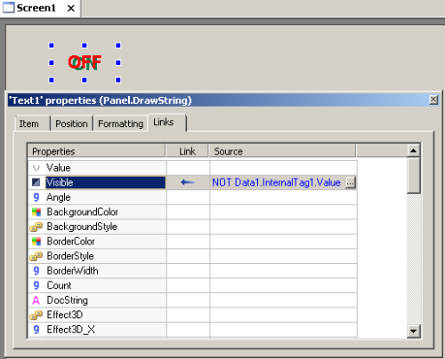
Figure 1: Incorrect settings for on/off pair
For only one on/off pair this may seem simple, but imagine something like:
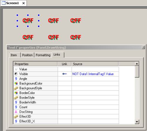
Figure 2: Incorrect settings for several on/off pairs
With only 6 pairs, we have 12 objects and 12 links. Notice that editing the application is then complicated because of the overlapping objects. For example, if the name of the tag linked in a pair is edited, it will have to be updated in its two links.
RECOMMENDED SOLUTION:
Create only one text object, with two links:
- Digital link between Value property and the tag; this property will display “On” when the tag is 1 and “Off” when it is 0.
- Digital link between TextColor property and the tag; this property will display green when the tag is 1 and red when it is 0.
This is how the digital link works with Value property:
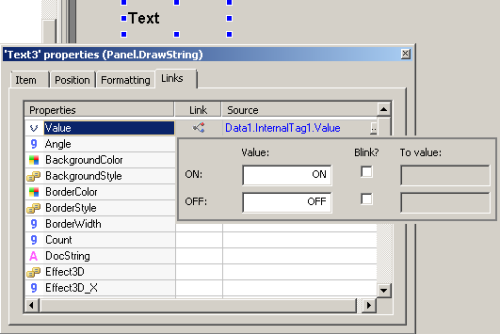
Figure 3: Value property’s correct settings for on/off pair
And this is how the digital link works with TextColor property:
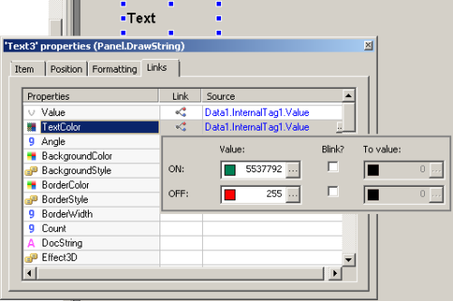
Figure 4: TextColor property’s correct settings for on/off pair
Similarly to the previous example, we will create five copies for viewing purposes:
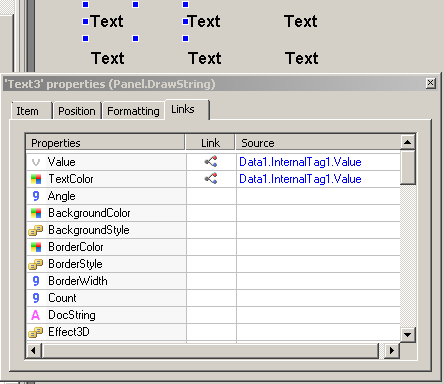
Figure 5: Correct settings for multiple on/off pairs
The benefits from creating links in only one object instead of two are:
- There are only six objects on screen.
- They are more easily edited now, because there are no overlapping objects and color settings are located in only one place.
- If the tag changes its name, you will only need to change the links in one object.
Still, the developer may wonder if changes couldn’t take place only once. This question will be solved later when discussing libraries.
PROBLEM 2:
How can I make a drawn truck scroll a pre-established path according to a tag’s value variation (digital, 0 to 3)?
UNRECOMMENDED SOLUTION:
Create four trucks (DrawPicture objects), and set a simple link in each tag’s Visible property, ranging the condition gradually, as follows:
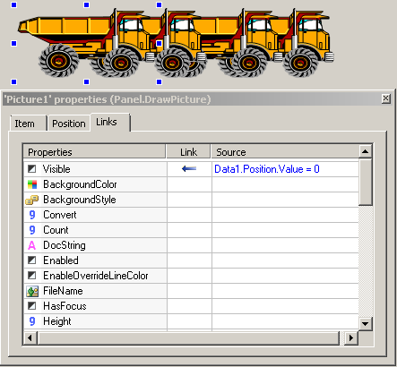
Figure 6: Incorrect settings for the first truck in the animation
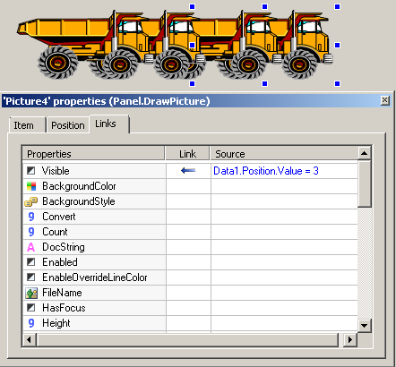
Figure 7: Incorrect settings for the last truck in the animation
This approach will work properly, but it is not an optimized one, because:
- It creates four links with the source (if the source changes, all four links must be edited as well).
- In case the tag’s precision is eventually increased, i.e., in case it has a larger number of combinations, you will need to create more trucks.
- In case the object’s initial position moves, the other objects must move as well.
A slightly improved solution is to have only one object with an analog link between the truck’s X property and the tag:
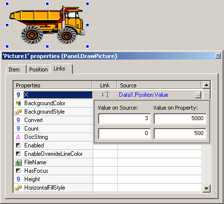
Figure 8: Slightly improved incorrect settings of the truck’s animation
As configured above, E3 will convert tag’s value to property’s value; therefore, when the tag varies from 0 to 3, values between 500 and 5000 will automatically be attributed to the truck’s X property, thus creating the movement.
However, this solution poses a question: how can I specify exactly when the animation will end? To fix this, see the next topic.
RECOMMENDED SOLUTION:
Select the image and click Animate with Translation button. E3Studio will then create a “ghost” image of the drawing indicating its final position. Remember that in the Organizer, the truck object is inside a new object called DynamicMove. We use the green square in the center of the object to position it where it is required.
Set up the DynamicMove‘s RangeMax and RangeMin properties to “3” and “0” respectively and create a simple link between Value property and the tag as seen below:
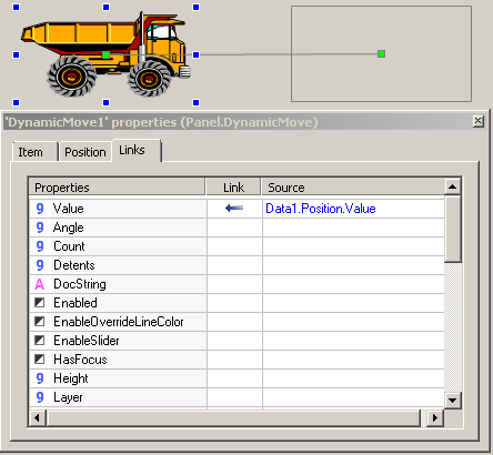
Figure 9: Correct settings for the truck’s animation
This will cause the object to slide automatically from one place to another, which is beneficial because:
- The “ghost” image indicates the truck’s final position in an intuitive, clear way.
- If you need to move the object’s initial position, the final position is automatically displaced.
- You can test the movement by changing DynamicMove‘s Value property when editing E3Studio.
PROBLEM 3:
How can I create an animation that displays a pump’s status as it changes its color? Example: a pump with three different statuses (“on”, “off”, and “in maintenance”) represented by the colors green, red, and grey, respectively.
UNRECOMMENDED SOLUTION:
Create three bitmaps with these three colors, and create a simple link between Visible property and the tag (similarly to Problem 1). Each bitmap’s color is set up as transparent:
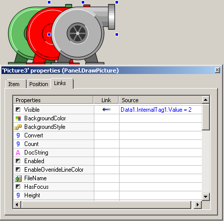
Figure 10: Incorrect settings for changing pump color
In this example, the pumps are displayed side by side for this article’s exposition purposes, because they should actually be overlapping. This approach is problematic because:
- We have three bitmaps, and whenever it needs to be redesigned, you will have to edit the three versions. For example: if the “on” status is changed to blue, the source bitmap will need to be edited.
- There are three links to the same tag; if tag name changes, it will need to be edited in the three links.
- Edition is also further complicated by the three overlapped objects.
RECOMMENDED SOLUTION:
When working in E3, always prefer WMF (Windows MetaFile) files, because their drawing features (such as color and fitting) can be edited without having to change the source file. To fix this, add the WMF to the screen and create a table link between OverrideFillColor property and the tag:
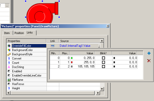
Figure 11: Correct settings for changing pump color
In addition to the benefits of this type of link (see Problem 1), using WMF files are preferred to using bitmaps because:
- You can set up the WMF fill mode via OverrideFillMode property as Wireframe, SolidFill, or ByBrightness.
- You can set up the WMF fill color.
- You can set up the WMF line color.
- This is a vector; therefore, it won’t lose in resolution even when zoomed in.
As stated before, all these changes in the image won’t affect the original file, only the way it is visualized.
For further information on applications with several configured objects, as well as on how to use these configurations, access Developing object-oriented applications in Elipse E3 – Part II.
