1) PLC Settings
The Programmable Logic Controller TP02 needs to be configured according to the port with which you want to perform the communication. It can either be via a MMI (RS422) port or a RS485 communication port.
To perform the system’s memory configurations and input the instructions (Ladder) into the PLC, you need to have the program PC12 Design Center installed in your computer. This program is supplied by Weg Automation.
RS485 Communication Port
To perform the communication via PLC’s RS485 port, the following system memory’s configuration is required:
WS043 – RS485 communication port function adjustment
0 = Computer connection
1 = Data connection
2 = Remote I/O
WS044 – Specification of RS485 communication port adjustment
Table 1 – Computer’s connection:
|
DATA SIZE |
STOP BIT |
PARIDADE |
BAUDRATE |
|
0:7 bits |
0:1 bit |
0:no |
0:19200 |
|
1:8 bits |
1:2 bits |
1:odd |
1:9600 |
|
|
|
2:even |
2:4800 |
|
|
|
|
3:2400 |
|
|
|
|
4:1200 |
|
|
|
|
5:600 |
|
|
|
|
6:300 |
|
|
|
|
7:38400 |
WS045 – RS485 communication port station adjustment (slave’s address on the network)
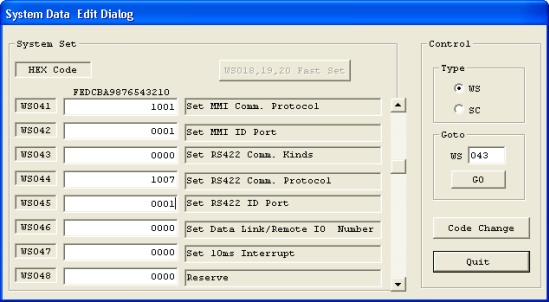
Picture 1 – Example of setting System Memory for RS485 port
For communication via RS485 port, you need a TP202PG cable (communication cable between the PLC and the computer), and an ADAM-4520 converser, or any other converser that converts RS232 signal into RS485 (default for RS485 port in TP02’s bornes).
To place a second PLC onto the network you must connect one T/R+ borne to the other in a PLC, as well as one T/R- borne to the other, so that the PLCs communicate to each other via RS485 protocol.
RS422 MMI Communication Port
The communication between TP02 and Elipse software can be made via the MMI port, however this is not recommended due to its low performance and distance limitation in RS422 standards.
For communication via PLC’s MMI port to happen, the following system memory’s configuration is required:
WS041 – MMI communication port adjustment
Table 2 –MMI communication port
|
DATA SIZE |
STOP BIT |
PARITY |
BAUDRATE |
|
0:7 bits |
0:1 bit |
0:no |
0:19200 |
|
1:8 bits |
1:2 bits |
1:odd |
1:9600 |
|
|
|
2:even |
2:4800 |
|
|
|
|
3:2400 |
|
|
|
|
4:1200 |
|
|
|
|
5:600 |
|
|
|
|
6:300 |
|
|
|
|
7:38400 |
WS042 – Communication port station adjustment (slave’s address on the network)
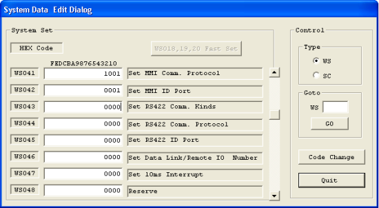
Picture 2 – Example of setting System Memory for MMI port
For communication via MMI port, it is necessary that pins 4 and 5 from TP202PG cable (communication cable between the PLC and the computer) are in short circuit directly in MMI port’s connector.
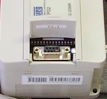
Picture 3: Jumper between MMI port’s pins 4 and 5
You will also need a TP232PG converser, which converts RS232 signal into RS422 (MMI) signal.
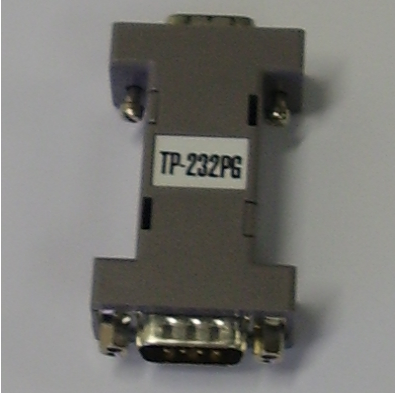
Picture 4: Converser TP-232PG
2) Supervisory Settings
Driver settings [P] parameter
- P1 – Serial port (10 = COM1; 20 = COM2; 30 = COM3; 40 = COM4) + data bits (0 = 7 bits; 1 = 8 bits)
- P2 – Parity (0 = no parity; 10 = odd; 20 = even) + baud rate (0 = 19200; 1 = 9600; 2 = 4800; 3 = 2400; 4 = 1200; 5 = 600; 6 = 300; 7 = 38400)
- P3 – Stop-bits (0 = 1-bit; 1 = 2-bits)
- P4 – Timeout (in milliseconds)
The parameter P1 is defined by adding the value of serial port to the value of data bits. The parameter P2 is defined by adding the value of baud rate to the value of parity.
PLC Tags address [N] parameter
- N1 – Slave address (1 to 99) + function (see Table 3)
- N2 – Time of response (see Table 4)
- N3 – Type of register (see Table 5)
- N4 – Register’s address (if necessary)
Tabela 3 – Driver functions
|
VALUE |
R/W |
FUNCTION |
|
0 |
R |
MCR (read only) |
|
0 |
W |
SCS (write only) |
|
100 |
R |
PSR (read only) |
|
200 |
W |
STP (write only) |
|
300 |
W |
RUN (write only) |
|
400 |
W |
RTC (write only) |
|
500 |
W |
WRV (write only) |
|
500 |
R |
MRV (read only) |
Table 4 – Time of response
|
N2 |
TIME(MS) |
|
0 |
0 |
|
1 |
10 |
|
2 |
20 |
|
3 |
30 |
|
4 |
40 |
|
5 |
50 |
|
6 |
60 |
|
7 |
70 |
|
8 |
80 |
|
9 |
90 |
|
10 |
100 |
|
11 |
200 |
|
12 |
300 |
|
13 |
400 |
|
14 |
500 |
|
15 |
600 |
Table 5 – Register Types (N3 parameter)
|
VALUE |
MCR/SCS |
WRV/MRV |
RTC |
|
0 |
X |
V |
RTC Stop |
|
1 |
Y |
D |
RTC Run |
|
2 |
C |
F |
30 seconds of offset correction |
|
3 |
Sc |
WS |
RTC Update* |
|
4 |
– |
WC |
|
NOTA: The function RTC Update is a pre-command which allows updating the RTC (RTC update data must be sent subsequently by the user, by writing data in V1018-V1024).
PLC Block addressing [B] parameters
B1 – Slave address (1 to 99) + function (see Table 3)
B2 – Time of response (see Table 4)
B3 – Type of register (0 = V; 1 = D; 2 = F; 3 = WS; 4 = WC)
B4 – Register’s address
NOTA: The functions available for block tags are WRV (write only) and MRV (read only), whose value is 500.
3) Related websites
http://www.weg.com.br/index.htm
http://www.elipse.com.br
