To establish communication between Arduino and Elipse E3 or Elipse SCADA, the hardware must be PLC- or RTU-like, that is, it must have a communication protocol that is programmed to transmit information retrieved by field devices (sensors, relays, etc.) to the supervisory.
In this article, we will illustrate this usage with Modicon Modbus, a commonly used communication protocol.
1) Setting up Arduino IDE
- Download Arduino IDE, available at their official website, on Download tab.
- Configure IDE to work with the device’s specific board and port. In the example (Figure 1), the Arduino UNO Rev3 is communicating via COM3.
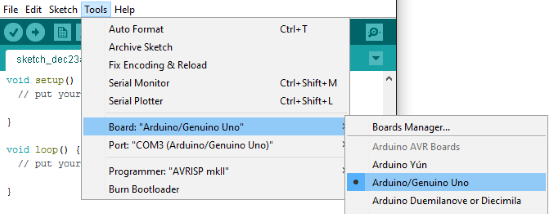
Figure 1: Choosing board and port in IDE.
2) Setting up Modbus Slave protocol in Arduino
After the physical settings, you must set up the hardware as a slave unit for the Modbus network. To do so, you will need a library with the protocol settings.
There are several Modbus Slave libraries available in the internet; for this article’s purposes, we chose arduino-modbus-slave, which can be downloaded from this site (or from the file attached to this article, in Arduino > ModbusSlave.zip).
- Export ModbusSlave library to IDE Arduino via Sketch > Include Library > Add .ZIP Library… (see Figure 2).
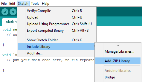
Figure 2: Inserting a library in IDE.
- Then, open ModbusSlave_0.ino file (also attached). This file’s code was inspired by this forum, and it can be edited as needed.
- Check ID Slave (regBank.setId(1)) and the pins’ distribution and parameterization. NOTE: keep BaudRate as 9600bps
- Compile the code. If successful, upload it to Arduino.
3) Setting up Modicon Modbus Master (ASC/RTU/TCP) driver
After setting up Arduino as the network’s slave, you will need to set up the master driver for communication.
- Download Modicon Modbus Master (ASC/RTU/TCP) driver from Elipse Software’s website.
- Add the driver to the application (E3 or Elipse SCADA), access its settings (IOKit) on Modbus tab and parameterize them as seen in Figure 3:

Figure 3: Modbus protocol settings.
- On Setup tab, set up PhysicalLayer property as Serial
- Set up Serial tab as seen in Figure 4. NOTE: if you use COM1 port to configure the Windows Device Manager and IDE, be sure to use it for the driver as well.

Figure 4: Serial tab settings.
- Finally, set the Operations up. To parameterize them, check these details:
a) Digital Output: Status will be read via Read Coil Status (0x) function and written via Force Single Coil (0x). This Operation is parameterized as follows:
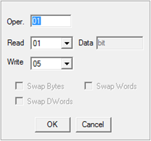
Figure 5: Digital Output settings.
b) Digital Input: Status will be read via Read Input Status (1x) function, and will not be written. This Operation is parameterized as follows:
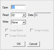
Figure 6: Digital Input settings.
c) Analog Input: Analog variables will be read via Read Input Registers (3x) function, and will not be written. This Operation is parameterized as follows:
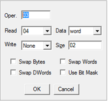
Figure 7: Analog Input settings.
d) Analog Output: Analog variables will be read via Read Holding Registers (4x) function and written via Preset Single Register (4x) function. This Operation is parameterized as follows:
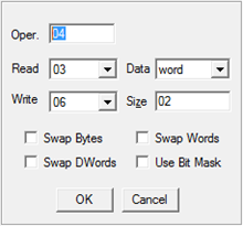
Figure 8: Analog Output settings
4) Setting up the driver’s I/O tags
To configure the I/O tags, follow the information in the driver’s manual or in the article Communication with Arduino.
Their parameters settings are:
N1: Slave device address (Arduino)
N2: Operational code (see previous section)
N3: Additional parameter, do not use (leave 0)
N4: Address of the Arduino device to be read/written
Digital Output settings (example):
Four digital outputs were configured in the Arduino code. See the code below with the set up Modbus function and output pins (ModbusSlave_0.ino file):
regBank.add(8);
regBank.add(9);
regBank.add(12);
regBank.add(13);
.
.
.
pinMode(8,OUTPUT);
pinMode(9,OUTPUT);
pinMode(12,OUTPUT);
pinMode(13,OUTPUT);
You can see that the code’s 8, 9, 12 and 13 addresses work as outputs. The tag’s settings are:
N1: 1 (Arduino’s Slave ID)
N2: 1 (Operation for digital outputs – see above)
N3: 0 (not used)
N4: 8 or 9 or 12 or 13 (address set up in the code)
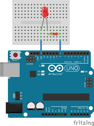
Figure 9: Arduino controlling a LED via digital output 8
Attached to this article are the following folders:
- Arduino: contains ModbusSlave.zip file (library) and ModbusSlave_0 folder, with ModbusSlave_o.ino file (code for Arduino)
- ArduinoModbus_E3: contains an Elipse E3 application
- ArduinoModbus_SCADA: contains an Elipse SCADA application
NOTES:
- The arduino-modbus-slave library’s license follows GNU LGPL guidelines.
- The values of digital and analog variables float continuously if nothing is plugged to these pins. Para contornar esta situação, deve-se aterrar os pinos de entrada que não forem utilizados.
Attachments:

Thank you so much for sharing this with us, it helps me a lot, I really appreciated it!