Operating under a concept of filter similar to the one in E3Alarm, Elipse Power’s Alarm Filters allows you to query a series of alarms statistics, among which we can mention a customized counter. This feature has been a part of Elipse Power since version 4.7.
The demo application discussed below, developed with Elipse Power version 4.7, contains three modeled substations. Their breakers’ and switches’ commands, measurements, and alarms have already been set up. Single-line screens are accessed from a menu screen. Menu buttons must be animated as follows:
- Whenever a user in COS group logs into the system, menu buttons must blink when a high-voltage alarm is active and unacknowledged.
- Whenever a user in Operator group logs into the system, menu buttons must blink when a low-voltage alarm is active and unacknowledged.
Since alarms have no preset field to return objects’ voltage, the first step is to create a user field reporting the voltage in each alarm’s parent object (breakers or switches, for example). To do so, follow these procedures:
1. On the Alarm Server’s User Fields tab, set up UserFiled1 as BaseVoltage. This field’s source won’t be set up at the Alarms Server, because sources pertain to their own alarms (that is, they won’t receive the value set up at the Alarms Server).
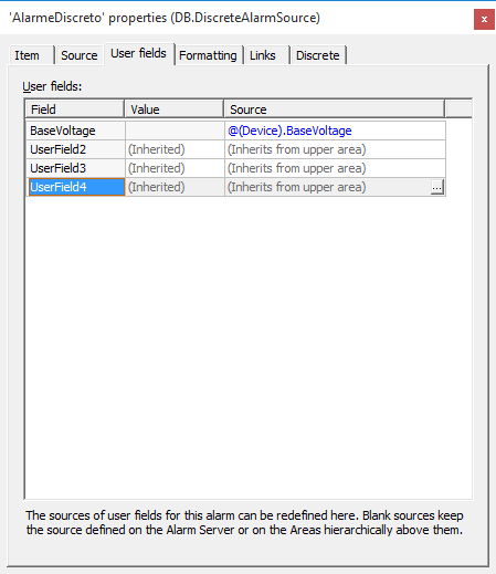
2. Set up the BaseVoltage field’s source in each alarm individually. To do so, access the User fields tab of the discrete alarms added to breakers’/switches’ BreakerPosition/SwitchPosition measurements, and set up BaseVoltage‘s source to retrieve its parents’ BaseVoltage property. The resulting expression is:
@(Device).BaseVoltage
The figure below illustrates how to set up the window associated to each alarm:
NOTE: You must configure the sources added to all BreakerPosition/SwitchPosition discrete measurements. This can be done via scripts or manually.
The second step is to implement the animation for each substation’s buttons. To do so will require the statistics pertaining each substation’s active and unacknowledged alarms; additionally, all alarms must be filtered by their parent object’s voltage (69 kV or 13,8 kV). To develop this filter, use the Alarm Filter as follows:
1. Create three Alarm Filters in the Viewer: SE1_Filter, SE2_Filter, and SE3_Filter.
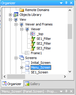
2. Set up each object’s AreaFilter property as SE1, SE2, and SE3, respectively.
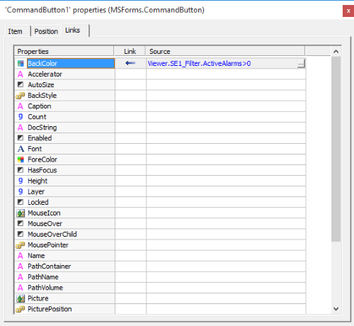
3. Alarm Filters feature a property called ActiveAlarms, which returns the number of alarms still active inside a given Area. To animate the button’s background color, create a digital link in each button’s BackColor property to test each filter’s ActiveAlarms property (value must be higher than 0). From there, set up the following expression in BackColor property’s Source field:
Viewer.SE1_Filter.ActiveAlarms > 0
The figure below illustrates this expression:
4. Click BackColor property’s Connection field and set up a digital link, as illustrated in the figure below:
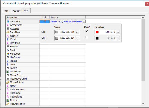
5. From this point on, the button will blink whenever there is an active alarm in the Area. Repeat these procedures for all buttons on menu screen, will their respective alarm filters.
The last step is to develop a script that tests to which group each user is logged (COS or Operator); from then on, set up the filters in each Alarm Filter created in the Viewer.
1. The Viewer’s OnLogin event contains a script that opens a frame. First, use IsMemberOfGroup method to establish to which group the user belongs:
Else
End if
2. Then, set up the alarms at the Alarm Filter according to their voltage levels. To do so, use CustomFilter property:
Item(“SE1_Filter”).CustomFilter = “BaseVoltage = 69”
Item(“SE2_Filter”).CustomFilter = “BaseVoltage = 69”
Item(“SE3_Filter”).CustomFilter = “BaseVoltage = 69”
Else
Item(“SE1_Filter”).CustomFilter = “BaseVoltage = 13.8”
Item(“SE2_Filter”).CustomFilter = “BaseVoltage = 13.8”
Item(“SE3_Filter”).CustomFilter = “BaseVoltage = 13.8”
End if
Application.GetFrame(“_top”).OpenScreen “Frame1”,0
3. The final script will look as follows:
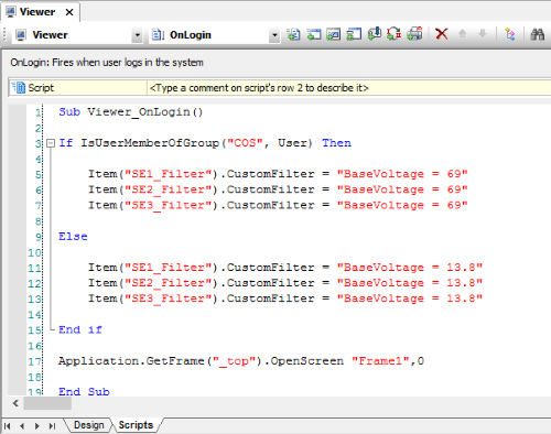
Finally, run the application and test its new features.
NOTES:
- User: elipse1 Password: elipse Group: COS
- User: elipse2 Password: elipse Group : Operator
- This application was developed with Elipse Power version 4.
